Of course with the arrival of version 9 comes a number of improvements and new features. This time the number is so large that we have had to split the post into two parts.
Completely made up studies have shown that it took some readers so long to read the entire post, their laptop batteries could not hold up.
Completely made up studies have shown that it took some readers so long to read the entire post, their laptop batteries could not hold up.
Walls
- In addition to the previous walls, there are now also the wall types “interior wall” and “installation wall”
- Interior walls and installation walls can be loaded using the "Insert" menu
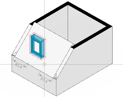
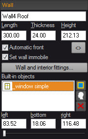
- Interior walls and installation walls can contain recesses and openings
- The front sides of interior walls and recesses can be given a front and a wall covering automatically
- Installation walls can generate an isle in the floor covering automatically as well as in the wall covering behind them
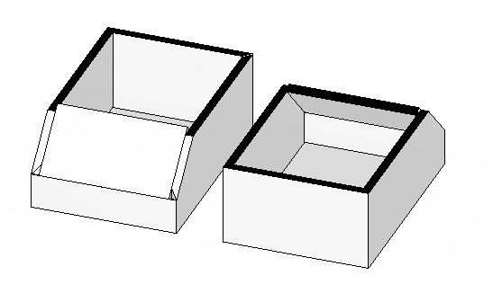
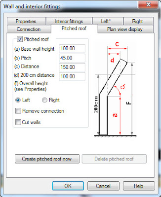
- An installation wall can adapt itself to a pitched roof located behind it
- When an installation wall or an interior wall is moved or modified, the floor covering and the wall covering are adapted accordingly
- The creation of a free wall contour has been simplified: The walls are always set working either from the inside or the outside
- Fronts and walls are no longer designated as “left/right” but as “internal/external” or “A/B”
- The input for a free wall contour with an internal angle has been revised and is now much more intuitive
- A free wall contour can create cameras in the corners automatically just like an intelligent room
- The intelligent base board has been removed from the “Insert” ribbon and can now be loaded as an object from the catalogues
Exposé
- The preview images show the image size, the name of the view and the selected display mode
- There are arrows, lines and geometric shapes, such as rectangles, triangles and circles to supplement the display on a sheet
- The views, bitmaps, texts and geometric shapes can align themselves with each other automatically on the sheet
- In addition, there is a grid for alignment purposes on the sheet
- Views can also be aligned using Align, 2 Points
- This is useful, for example, when a front view needs to be aligned with a plan view
- Default settings are managed centrally in one dialog box
- The quality (resolution) of the rendered views is now also taken from the default settings and no longer from the printer used
- The layout of a page can be saved as a template
- Drawing frames can be drawn and saved
- However, drawing frames that have been drawn only fit on the sheet for which they were drawn
- The previous parametric drawing frames which adapt themselves to the sheet are still available
- Bitmaps can contain transparent and semi-transparent areas (e.g. for watermarks)
- The Exposé can be output as a PDF
- During output as a PDF, it is possible to select the pages which are to be included in the output
- All of the views defined in the scene (plan views, front views, cameras) can be selected from a menu and inserted into the Exposé
- Front views can be joined to produce unfolded wall views either automatically or manually
- The general quality of the graphic display in the Exposé has been improved
- The settings in the context menu have been rearranged for a clearer overview
Catalogue management
- When catalogues are installed on several different drives (e.g. locally and on a server), the drives are now shown individually in the object browser (as was previously already the case in the materials browser)
- There are material and object catalogues which contain an Internet link
- This makes it possible to load and install catalogues via this link that are not included in delivery with Palette CAD but must instead be downloaded from a manufacturer
Catalogue updates via the Cloud
- Object catalogues and material catalogues can be updated via the Internet automatically on a regular basis
- There is an update manager for this purpose which runs in the background and checks the Palette web server for new catalogues that are licensed by the user and downloads these
- The update manager can be enabled and configured via File / Updates as well as via the Windows taskbar
- Of course, catalogues can still be installed and updated as previously using a DVD and an installation program
Doors
- For doors, the insertion point that is appropriate for the selected dimension input type (outer dimensions, rough dimensions or door leaf width) is now used as a matter of course
- With automatic door dimensioning, the dimensioning is adapted to match the selected type of dimension input
Dimensioning
- Dimensioning has been completely reworked and the feature is now much more powerful, faster and easier to use
- There is a management area for dimensioning styles
- Dimensioning styles can be changed globally for an entire drawing
- A scale can be defined for dimensioning so that the size of the dimensions can be set in page coordinates that are standards compliant
- Automatic dimensioning for drawings is now easier and faster
- You can assign a dimensioning type to objects intended for automatic dimensioning (e.g. outer dimension or centred)
Measuring
- The Measuring function has been revised and can now be operated significantly faster with fewer mouse clicks
- It is now possible to measure lengths and angles on faces in the room in the axonometric view
Drawing
- There is a new menu called "Draw"
- The “Draw” menu must be licensed as a separate function module. The previous licence for “Palette CAD 2D” automatically licenses the “Draw” feature
- “Draw” replaces many functions from the previous “Palette CAD 2D” add-on program and is integrated seamlessly into Plan 3D
- The truly unique feature of “Draw” is that you can draw and design right in the scene just as you would on a sheet of paper
- As is customary for 2D programs, the sequence for operations is the reverse of that for 3D objects: You must first select a function, such as trimming, and then use it on the drawing element
- Line thicknesses can be set in mm
- However, the line thickness is only used for output formats (Exposé, printouts). In the scene itself, lines are always displayed uniformly thin
- There are 2D elements, such as lines, freehand lines, splines, polylines, rectangles, circles, arcs, ellipses and elliptical arcs with an array of useful means for constructing them
- 2D can be trimmed, extended, divided, edited and joined to form polylines
- There are 2D guide lines
- Corners can be chamfered, rounded and filleted
- Line contours created in “Draw” can be converted into these 3D objects: extrusion, board and wood technology board
- There is very useful function in the axonometric view called “Align axonometric view”
- When you click on a face in the axonometric view, this function rotates the axonometric in the view so that the face lies exactly in the drawing plane
- This allows you to do design work on this face. This means that Align works like a user coordinate system for 2D designs
- 2D elements can be derived from the edges of 3D objects so that these elements can be used for 2D designs, for example
- The display of a scene in the plan view and in the front view can also be converted in its entirety to a 2D drawing, allowing the drawing and the line styles to be edited
- A display with perspective and an axonometric view can be converted to a 2D drawing so that the individual lines can be edited
- There are new display modes for 2D elements in the “edge view" and "wire frame model” display modes
- There is a new display mode in which 3D objects are greyed out and cannot be selected
- There is a display mode in which only 2D elements are shown
- Drawing is possible in the plan view, front view and axonometric view display windows. Drawing is not possible in the perspective view
- A new snap function is called “Point of contact” and it can be used to snap tangents on 2D curves
- The lines used in Palette CAD up until now are 3D lines because they can be placed freely in space and are not limited to placement on a flat surface
- This means there are now two line types in Palette CAD: 2D lines and 3D lines
Hatch
- Hatches can be used in the “Draw” ribbon
- A scale can be defined for hatches so that the size of the hatching can be set in page coordinates that are standards compliant
- There is now a management area for professional hatch styles
- Hatch styles can be line patterns, free patterns and bitmaps
- Hatches can be aligned and scaled in the scene
- You can create your own hatch styles
- In the axonometric view, hatches can also be placed on faces in the room
Import and export
- The import of DXF and DWG has been completely revised and can now include complete 2D working drawings with dimensioning and hatches
- The formats DWF (Design Web Format) and DGN (Microstation) can be imported
- 3D export has been expanded to include the DXF and Collada formats
- The output for 3D printers in the STL format has been improved
- There is a PDF export
- The 2D export filters double lines
- The 2D DXF export can be linked to external 2D programs in such a way that the program is opened automatically with the imported DXF file
- The import of architectural plans in the BIM format (ifc) from BIM-capable architecture programs has been expanded and improved to include additional elements
Primitives
- The cuboid can now also be loaded as a rectangular canal
The Bool Subtraction operation
- Bool subtraction for objects has been improved and now works in many instances in which it was previously not possible
Palette Cloud
- The available memory and the maximum storage period depend on the Palette CAD service agreement that is held
- Proxy servers are also supported

That's it for part one. Make sure to check back next month for the rest of the list. Enjoy!
Greeting from Stuttgart,
Your Palette CAD Blog Team